Unit 2
1) Name and categorizes different multiple access protocols.
Multiple access protocols are used in computer networks to manage the sharing of a common communication channel among multiple devices. Here are some of the main types of multiple access protocols:
1. ALOHA
- Type: Unslotted ALOHA
- Description: A simple, uncoordinated multiple access protocol where each station transmits a packet as soon as it has one to send.
- Advantages: Easy to implement and requires no coordination.
- Disadvantages: High collision rate due to lack of coordination.
2. Slotted ALOHA
- Type: Slotted ALOHA
- Description: A variant of ALOHA where the transmission slots are synchronized, reducing the collision rate.
- Advantages: Better throughput than unslotted ALOHA.
- Disadvantages: Still has a high collision rate due to lack of coordination.
3. Carrier Sense Multiple Access (CSMA)
- Type: CSMA
- Description: A protocol where each station senses the channel before transmitting. If the channel is busy, the station waits for a random period before trying again.
- Advantages: Reduces collisions by allowing stations to wait before transmitting.
- Disadvantages: Can lead to collisions if multiple stations sense the channel as idle at the same time.
4. CSMA/CD
- Type: CSMA/CD
- Description: A variant of CSMA where a station that detects a collision during transmission immediately transmits a jam signal to inform other stations and then waits for a random period before retransmitting.
- Advantages: Fast recovery from collisions.
- Disadvantages: Can lead to collisions if multiple stations detect a collision at the same time.
5. Token Passing
- Type: Token Passing
- Description: A protocol where a special token is passed from one station to another. Only the station holding the token can transmit.
- Advantages: Ensures that only one station transmits at a time, reducing collisions.
- Disadvantages: Requires a token to be passed around, which can lead to delays.
6. Polling
- Type: Polling
- Description: A protocol where a central station (master) polls each station in turn to determine if it has data to send.
- Advantages: Ensures that only one station transmits at a time, reducing collisions.
- Disadvantages: Centralized control can lead to bottlenecks and single points of failure.
7. Random Access Memory (RAM)
- Type: RAM
- Description: A protocol where each station has a random access memory (RAM) that stores the packets to be transmitted. The station transmits the packets in a random order.
- Advantages: Reduces collisions by spreading out the transmission times.
- Disadvantages: Can lead to collisions if multiple stations transmit at the same time.
8. Time Division Multiple Access (TDMA)
- Type: TDMA
- Description: A protocol where the channel is divided into time slots, and each station is assigned a specific time slot to transmit.
- Advantages: Ensures that only one station transmits at a time, reducing collisions.
- Disadvantages: Requires precise synchronization and can lead to inefficiencies if not all time slots are used.
9. Frequency Division Multiple Access (FDMA)
- Type: FDMA
- Description: A protocol where the channel is divided into frequency bands, and each station is assigned a specific frequency band to transmit.
- Advantages: Allows multiple stations to transmit simultaneously without interference.
- Disadvantages: Requires careful frequency planning and can lead to inefficiencies if not all frequency bands are used.
10. Code Division Multiple Access (CDMA)
- Type: CDMA
- Description: A protocol where each station is assigned a unique code, and the data is spread across the entire frequency band using that code.
- Advantages: Allows multiple stations to transmit simultaneously without interference.
- Disadvantages: Requires complex encoding and decoding procedures.
These multiple access protocols are used in various networks, including local area networks (LANs), wireless networks, and satellite networks, to manage the sharing of the communication channel and ensure efficient data transmission.
2) Compare and explain the pure and slotted ALOHA system.
The pure ALOHA and slotted ALOHA are two different multiple access protocols used in computer networks:
Pure ALOHA:
- In pure ALOHA, a station transmits a frame as soon as it has data to send, without any coordination with other stations.
- If two or more stations transmit at the same time, a collision occurs, and the frames are corrupted.
- After a collision, each station waits a random amount of time before retransmitting the frame.
- The efficiency of pure ALOHA is limited to about 18% due to the high collision rate.
Slotted ALOHA:
- Slotted ALOHA is an improvement over pure ALOHA, where time is divided into discrete slots.
- Stations are only allowed to start transmitting at the beginning of a time slot.
- If two or more stations transmit in the same slot, a collision occurs, and the frames are corrupted.
- After a collision, each station waits a random number of slots before retransmitting the frame.
- The efficiency of slotted ALOHA is higher than pure ALOHA, reaching up to 36%, as the probability of collisions is reduced by synchronizing the transmissions.
The key differences between pure ALOHA and slotted ALOHA are:
- Timing:
- Pure ALOHA has no timing constraints, stations can transmit frames at any time.
- Slotted ALOHA requires stations to transmit only at the beginning of a time slot.
- Collision probability:
- In pure ALOHA, a collision can occur at any time, leading to a higher collision rate.
- In slotted ALOHA, collisions can only occur at the beginning of a time slot, reducing the probability of collisions.
- Efficiency:
- The efficiency of pure ALOHA is limited to around 18%.
- The efficiency of slotted ALOHA is higher, reaching up to 36%.
In summary, slotted ALOHA improves upon pure ALOHA by introducing time slots and synchronizing the transmissions, which reduces the probability of collisions and increases the overall efficiency of the protocol.
3) Explain different CSMA protocols.
There are several variants of Carrier Sense Multiple Access (CSMA) protocols:
- Non-persistent CSMA:
- When a station has a frame to send, it first listens to the channel.
- If the channel is busy, the station waits a random amount of time and then repeats the process.
- If the channel is idle, the station transmits immediately.
- 1-persistent CSMA:
- When a station has a frame to send, it first listens to the channel.
- If the channel is idle, the station transmits immediately.
- If the channel is busy, the station keeps listening until the channel becomes idle, then transmits immediately.
- p-persistent CSMA:
- Used for slotted channels, where time is divided into discrete slots.
- When a station has a frame to send, it listens to the channel.
- If the channel is idle, the station transmits with probability p, and defers until the next slot with probability 1-p.
- If the channel is busy, the station defers until the next slot and repeats the process.
- CSMA/CD (Collision Detection):
- Used in wired LANs like Ethernet.
- When a station has a frame to send, it listens to the channel.
- If the channel is idle, the station transmits immediately.
- If a collision is detected during transmission, the station immediately aborts the transmission and sends a jam signal.
- The station then waits a random time before attempting retransmission.
- CSMA/CA (Collision Avoidance):
- Used in wireless LANs like IEEE 802.11 (Wi-Fi).
- When a station has a frame to send, it listens to the channel.
- If the channel is idle for a specified time, the station transmits.
- If the channel is busy, the station defers until the channel is idle and then waits a random backoff time before attempting retransmission.
The main differences between these protocols are:
- The actions taken when the channel is busy or idle
- Whether collisions are detected during transmission
- The use of slotted time or random backoff periods
The choice of CSMA protocol depends on factors such as the network topology, the expected traffic load, and the ability to detect collisions during transmission.
4) What is CSMA/CA?
CSMA/CA (Carrier Sense Multiple Access with Collision Avoidance) is a media access control (MAC) protocol used in wireless networks, such as IEEE 802.11 (Wi-Fi), to manage the sharing of the communication channel among multiple devices. It is designed to avoid collisions that occur when two or more stations transmit simultaneously.
Here’s how CSMA/CA works:
- When a station has a frame to send, it first listens to the channel to check if it is idle.
- If the channel is idle for a specified time (called DIFS - Distributed Inter-Frame Space), the station can begin transmitting the frame.
- If the channel is busy, the station defers transmission and enters a backoff process:
- The station generates a random backoff time within a contention window.
- The station decrements the backoff timer as long as the channel is sensed as idle.
- If the channel is sensed as busy during the backoff process, the station freezes the backoff timer until the channel is sensed as idle again for a DIFS duration.
- When the backoff timer reaches zero, the station can transmit the frame.
- If the destination station successfully receives the frame, it waits for a short inter-frame space (SIFS) and then transmits an acknowledgment (ACK) frame back to the sender.
- If the sender does not receive the ACK within a specified time, it assumes a collision occurred and retransmits the frame after a random backoff time.
The main differences between CSMA/CD (Collision Detection) and CSMA/CA are:
- CSMA/CD is used in wired networks like Ethernet, while CSMA/CA is used in wireless networks.
- CSMA/CD can detect collisions during transmission, while CSMA/CA cannot, as wireless stations cannot transmit and receive simultaneously.
- CSMA/CA relies on collision avoidance mechanisms, such as random backoff and ACKs, to reduce the probability of collisions.
By using random backoff times and deferring transmission when the channel is busy, CSMA/CA helps to reduce the probability of collisions in wireless networks, improving overall performance and fairness in channel access.
5) What is CSMA/CD? Explain with Flow chart.
CSMA/CD (Carrier Sense Multiple Access with Collision Detection) is a media access control (MAC) protocol used in Ethernet networks to manage the sharing of the communication channel among multiple devices. It is designed to detect and handle collisions that occur when two or more stations transmit simultaneously.
Here’s how CSMA/CD works, along with a flowchart:
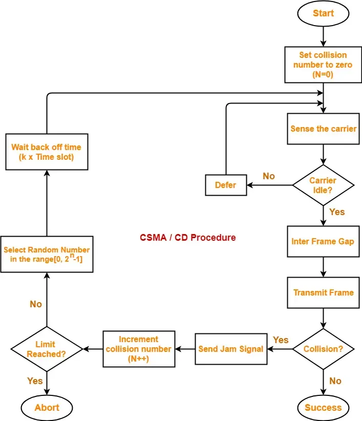
- Before transmitting, a station listens to the channel to check if it is idle.
- If the channel is idle, the station begins transmitting the frame.
- While transmitting, the station continues to monitor the channel for collisions.
- If a collision is detected, the station immediately aborts the transmission and sends a jam signal to notify other stations of the collision.
- After sending the jam signal, the station waits a random backoff time before attempting to retransmit the frame.
- If the channel is still busy after the backoff time, the station defers transmission until the channel becomes idle again.
- If no collision is detected, the station completes the transmission of the frame.
The random backoff time is calculated using a binary exponential backoff algorithm, which increases the backoff time exponentially with each successive collision. This helps to reduce the probability of repeated collisions and ensures fair access to the channel.
CSMA/CD is an effective protocol for managing collisions in Ethernet networks, especially in shared media environments like early Ethernet networks. However, as Ethernet evolved to use switches instead of hubs, collisions became less common, and the need for collision detection became less important. Modern Ethernet networks use CSMA/CA (Carrier Sense Multiple Access with Collision Avoidance) instead, which focuses on collision avoidance rather than detection.
6) Explain Manchester encoding for the bit stream 1001110100.
Manchester Encoding
Definition: Manchester encoding is a method of encoding binary data in which each bit of data is represented by a transition in the signal. It combines clock and data information, ensuring synchronization between the sender and receiver. In Manchester encoding, a logical “1” is represented by a high-to-low transition, and a logical “0” is represented by a low-to-high transition.
Encoding the Bit Stream 1001110100
Let’s break down the bit stream 1001110100 using Manchester encoding:
- Bit Representation:
- 1: High to Low transition
- 0: Low to High transition
- Encoding Process:
- For each bit in the input stream, we will draw the corresponding Manchester encoded waveform.
Step-by-Step Encoding:
- Bit 1: 1 → High to Low transition
- Bit 0: 0 → Low to High transition
- Bit 0: 0 → Low to High transition
- Bit 1: 1 → High to Low transition
- Bit 1: 1 → High to Low transition
- Bit 1: 1 → High to Low transition
- Bit 0: 0 → Low to High transition
- Bit 1: 1 → High to Low transition
- Bit 0: 0 → Low to High transition
- Bit 0: 0 → Low to High transition
Manchester Encoding Representation:
Here’s how the Manchester encoding for the bit stream 1001110100 would look in a waveform representation:
- 1: High to Low transition
- 0: Low to High transition
- 0: Low to High transition
- 1: High to Low transition
- 1: High to Low transition
- 1: High to Low transition
- 0: Low to High transition
- 1: High to Low transition
- 0: Low to High transition
- 0: Low to High transition
Waveform Representation:
Time:   0    1    2    3    4    5    6    7    8    9   10
Bits:   1    0    0    1    1    1    0    1    0    0
Signal: ----|    |----|    |----|    |----|    |----|    |----
         High  Low  High  Low  High  Low  High  Low  High  Low
Summary
- Manchester Encoding: Each bit is represented by a transition; “1” is a high-to-low transition, and “0” is a low-to-high transition.
- Bit Stream
1001110100: The encoded waveform consists of alternating high and low states based on the transitions defined by the original bit stream.
This encoding method helps in maintaining synchronization between the transmitter and receiver, making it a popular choice in various communication systems.
7) How CSMA/CA differs from CSMA/CD. Explain in brief.
CSMA/CA (Carrier Sense Multiple Access with Collision Avoidance) and CSMA/CD (Carrier Sense Multiple Access with Collision Detection) are two different media access control (MAC) protocols used in computer networks to manage the sharing of the communication channel among multiple devices. The main differences between the two protocols are:
- Network Type:
- CSMA/CD is used in wired networks like Ethernet.
- CSMA/CA is used in wireless networks, such as IEEE 802.11 (Wi-Fi).
- Collision Detection:
- In CSMA/CD, stations can detect collisions during transmission by monitoring the channel.
- In CSMA/CA, stations cannot detect collisions during transmission, as they cannot transmit and receive simultaneously.
- Collision Handling:
- In CSMA/CD, when a collision is detected, the stations immediately abort the transmission, send a jam signal, and then wait a random backoff time before retransmitting.
- In CSMA/CA, stations use collision avoidance mechanisms, such as random backoff and acknowledgments (ACKs), to reduce the probability of collisions.
- Backoff Mechanism:
- In CSMA/CD, the backoff time is calculated using a binary exponential backoff algorithm, which increases the backoff time exponentially with each successive collision.
- In CSMA/CA, stations generate a random backoff time within a contention window and decrement the backoff timer as long as the channel is sensed as idle.
- Acknowledgments:
- In CSMA/CD, there are no explicit acknowledgments, as the stations assume successful transmission if no collision is detected.
- In CSMA/CA, the destination station sends an ACK frame back to the sender after successfully receiving a frame, allowing the sender to determine if a collision occurred.
By using random backoff times, deferring transmission when the channel is busy, and relying on acknowledgments, CSMA/CA helps to reduce the probability of collisions in wireless networks, improving overall performance and fairness in channel access. In contrast, CSMA/CD relies on collision detection and immediate retransmission after collisions, which is more suitable for wired networks with lower latency.
8) Explain Reservation, Token Passing and POLLING.
Reservation, Token Passing, and Polling
In computer networks, particularly in the context of medium access control (MAC) protocols, various methods are employed to manage how devices share the communication medium. Three common techniques are Reservation, Token Passing, and Polling. Below is an explanation of each method:
1. Reservation
Definition: Reservation is a technique used in network communication where a device requests permission to use the communication medium for a specific period. This is often done before actual data transmission occurs.
How It Works:
- A device sends a reservation request to the network to indicate its intention to transmit data.
- The network controller or a central authority evaluates the request and grants permission if the medium is available.
- Once the reservation is confirmed, the device can transmit its data without contention from other devices for the reserved time slot.
Advantages:
- Reduces collisions since devices have reserved time slots for transmission.
- Guarantees bandwidth for applications that require consistent data rates, such as video streaming.
Disadvantages:
- Can lead to underutilization of the medium if reservations are not fully used.
- Overhead in managing reservations can increase latency.
2. Token Passing
Definition: Token passing is a method where a special data packet, called a “token,” circulates in the network. Only the device that holds the token is allowed to transmit data.
How It Works:
- A token is passed from one device to the next in a predetermined order.
- When a device receives the token, it can send its data. After transmission, it passes the token to the next device in the sequence.
- If a device has no data to send, it simply passes the token to the next device.
Advantages:
- Reduces collisions since only one device can transmit at a time.
- Fair access to the medium, as each device gets the opportunity to send data.
Disadvantages:
- If the token is lost or corrupted, it can disrupt communication until a new token is generated.
- The overhead of managing the token can introduce delays.
3. Polling
Definition: Polling is a technique where a central controller (master) sequentially checks each device (slave) in the network to see if it has data to send.
How It Works:
- The master device sends a request to each slave device in turn, asking if it has data to transmit.
- Each slave responds to the master, either indicating that it has data to send or that it is idle.
- If a slave has data, the master allows it to transmit before moving on to the next device.
Advantages:
- Efficient use of the medium since only devices with data can transmit.
- Simple implementation and management, especially in small networks.
Disadvantages:
- Can introduce latency, especially if many devices are polled and only a few have data to send.
- The master device can become a bottleneck if it is overwhelmed with requests.
Conclusion
Each of these methods—Reservation, Token Passing, and Polling—has its own advantages and disadvantages, making them suitable for different types of networks and applications. Understanding these techniques is essential for network engineers and administrators to design efficient communication systems.
9) Explain Binary back off algorithm.
Binary Backoff Algorithm
Definition: The Binary Backoff Algorithm is a method used in networking to manage contention among multiple devices trying to access a shared communication medium. It is particularly associated with protocols like Carrier Sense Multiple Access with Collision Detection (CSMA/CD), which is used in Ethernet networks.
How It Works:
- Collision Detection:
- When two or more devices attempt to transmit data simultaneously, a collision occurs. Each device detects the collision through the signals on the medium.
- Backoff Time Calculation:
- After detecting a collision, each device must wait for a random amount of time before attempting to retransmit. The Binary Backoff Algorithm determines this wait time.
- The backoff time is calculated based on the number of collisions that have occurred. Specifically, the backoff period increases exponentially with each subsequent collision.
- Exponential Growth:
- The algorithm uses a binary exponential backoff strategy, where the wait time is chosen from a range of values that doubles with each collision.
- For example, if a device experiences its first collision, it will wait for a random time between 0 and (0 to 1 time slots). If it experiences a second collision, it will wait for a random time between 0 and (0 to 3 time slots), and so on, up to a maximum limit.
- Maximum Attempts:
- The algorithm typically has a limit on the number of attempts a device can make to transmit after collisions. If the maximum number of attempts is reached without successful transmission, the device may give up or report an error.
Example of Binary Backoff:
- First Collision:
- Device A and Device B both transmit at the same time, causing a collision.
- Both devices calculate a backoff time, choosing randomly between 0 and 1 time slot.
- Second Collision:
- If both devices collide again after their backoff period, they will now choose a backoff time randomly between 0 and 3 time slots (0 to ).
- Subsequent Collisions:
- This process continues, with the range of possible backoff times doubling after each collision until a maximum limit is reached (commonly 16 attempts).
Advantages of Binary Backoff:
- Reduced Collisions: By introducing randomness in the backoff times, the likelihood of repeated collisions is decreased, improving overall network efficiency.
- Fairness: The algorithm provides a fair chance for all devices to access the medium, as each device has a random wait time.
Disadvantages of Binary Backoff:
- Increased Latency: In high-collision scenarios, the backoff time can increase significantly, leading to delays in data transmission.
- Complexity: The algorithm requires devices to maintain state information about the number of collisions and calculate backoff times, adding some complexity to the implementation.
Conclusion
The Binary Backoff Algorithm is an essential mechanism for managing access to shared communication channels in networks, particularly in environments where collisions are common. Its design helps balance efficiency and fairness, making it a widely used strategy in network protocols.
10)Compare static vs dynamic channel allocation.
Here is a comparison of static and dynamic channel allocation in wireless networks:
Static Channel Allocation
- Channels are permanently assigned to cells or base stations
- Channels are reused in cells that are sufficiently far apart to avoid interference
- Channel assignment is done during network planning and remains fixed
- Simpler to implement as no dynamic allocation is needed
- Inefficient use of channels as demand may vary across cells
- Channels are underutilized in low demand cells and insufficient in high demand cells
Dynamic Channel Allocation
- Channels are temporarily assigned to cells or base stations based on demand
- Channels can be borrowed from neighboring cells that have excess capacity
- Channel assignment changes dynamically based on traffic load and interference conditions
- More complex implementation as channels need to be monitored and reallocated
- Efficient use of channels as they are allocated based on real-time demand
- Channels are shared across cells to match the varying traffic load
- Requires coordination between cells to avoid interference when borrowing channels
The key differences are:
- Channel Assignment: Static is fixed, dynamic is based on real-time demand
- Efficiency: Static can lead to underutilization, dynamic adapts to load variations
- Complexity: Static is simpler, dynamic requires monitoring and coordination
- Interference: Static reuses channels based on fixed reuse distance, dynamic needs to avoid interference when borrowing channels
Dynamic channel allocation provides more efficient use of spectrum but requires more sophisticated mechanisms to monitor load, coordinate channel borrowing, and avoid interference. The choice depends on the specific network requirements and the trade-offs between efficiency, complexity and performance.
11) Explain frame format specified by IEEE 802.3 standard contains following fields.
Frame Format Specified by IEEE 802.3 Standard
The IEEE 802.3 standard defines the frame format for Ethernet networks, which is used for data communication over local area networks (LANs). The frame consists of several fields that serve different purposes in the transmission of data. Below is an explanation of the key fields in the IEEE 802.3 frame format:
1. Preamble (7 bytes)
- Description: The preamble is a sequence of alternating 1s and 0s that helps synchronize the receiver’s clock with the sender’s clock. It consists of 56 bits (7 bytes).
- Purpose: It prepares the receiving device to recognize the start of the frame and allows for clock synchronization.
2. Start Frame Delimiter (SFD) (1 byte)
- Description: The SFD is a special byte (10101011) that indicates the start of the actual frame data.
- Purpose: It marks the end of the preamble and signals the beginning of the frame.
3. Destination MAC Address (6 bytes)
- Description: This field contains the MAC address of the intended recipient of the frame.
- Purpose: It ensures that the frame is delivered to the correct destination device on the network.
4. Source MAC Address (6 bytes)
- Description: This field contains the MAC address of the sender of the frame.
- Purpose: It allows the recipient to identify the source of the frame and facilitates communication back to the sender.
5. Length/Type (2 bytes)
- Description: This field can indicate either the length of the data payload (if the value is less than or equal to 1500) or the type of protocol being used (if the value is greater than 1536).
- Purpose: It helps the receiving device understand how to process the data that follows.
6. Data and Padding (46-1500 bytes)
- Description: This field contains the actual data being transmitted. If the data is less than 46 bytes, padding is added to meet the minimum frame size of 64 bytes.
- Purpose: It carries the payload of the frame, which can be any type of data (e.g., IP packets).
7. Frame Check Sequence (FCS) (4 bytes)
- Description: The FCS is a cyclic redundancy check (CRC) value used for error detection.
- Purpose: It allows the receiving device to verify the integrity of the received frame. If the FCS does not match the calculated value, the frame is discarded.
Summary of IEEE 802.3 Frame Format
| Field | Size (Bytes) | Description |
|---|---|---|
| Preamble | 7 | Synchronization sequence for the receiver |
| Start Frame Delimiter | 1 | Indicates the start of the frame |
| Destination MAC Address | 6 | MAC address of the intended recipient |
| Source MAC Address | 6 | MAC address of the sender |
| Length/Type | 2 | Indicates length of data or type of protocol |
| Data and Padding | 46-1500 | Actual data being transmitted, with padding if needed |
| Frame Check Sequence | 4 | CRC for error detection |
Conclusion
The IEEE 802.3 frame format is essential for the functioning of Ethernet networks, providing a structured way to encapsulate data for transmission. Understanding this frame format is crucial for network engineers and administrators involved in designing and troubleshooting Ethernet networks.